Products
Contact Us
- Contact Person : Mr. Chris Zhuang
- Company Name : Shanghai Reyo Electric Equipment Co., Ltd.
- Tel : 86-21-58754297
- Fax : 86-21-58754297
- Address : Shanghai,Shanghai,Rm. 103, Bld. 31, Lane. 12, Rd. Pusan, Dist. Pudong, Shanghai
- Country/Region : China
- Zip : 200125
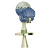
Level Transmitter Rosemount 5400 Series
Product Detailed
Related Categories:Level Measuring Instruments
Detailed Product Description
The 5400 Series transmitter is used for level
measurements on liquids and slurries with various
temperatures, pressures and vapor gas mixtures.
Because of its advanced surface tracking capability,
the transmitter can detect and evaluate all echoes
within the tank.
The Rosemount 5400 Series is easily configured for
a wide range of applications and process conditions.
In addition, it incorporates advanced signal
processing and smart echo tracking features.
Innovative design. Best-in-class performance
Non-contacting, making it virtually unaffected
by process conditions
No moving parts, means little or no
maintenance
Application flexibility with full range of
antennas, and two models 5402 (26 GHz) and
5401 (6 GHz)
Less affected by coating with Condensation
Resistant Antenna
Reduced echoes from obstacles / tank walls
with Circular Polarization
Powerful, easy-to-use configuration tool
withMeasure-and-Learn function
Specifications
General
Product Rosemount 5400 Series Radar Level Transmitter
Measurement Principle Pulsed, free propagating radar
5402: ~26 GHz
5401: ~6 GHz
Microwave Output Power < 1 mW
Beam Angle See table on page 12
Re-calibration Not required due to self-adjusting electronics.
Measuring Performance
Maximum Measuring Range 115 ft (35 m) from flange
Instrument Accuracy at reference
conditions(1)
5402: ± 0.1 in. (± 3 mm)
5401: ± 0.4 in. (± 10 mm)
Repeatability ± 0.04 in. (± 1 mm) at 16.4 ft (5 m) distance
Resolution 0.04 in. (1 mm)
Near Zone Distance 1.3 ft (0.4 m) from lower end of the antenna
Near Zone Accuracy 5402: ± 0.6 in. (± 15 mm)
5401: ± 1.2 in. (± 30 mm)
Transition Zone(2) 6 in. (150 mm) from lower end of the antenna
Minimum Dielectric Constant εr = 1.4
Temperature Drift 0.05 %/10 K in temperature range -40°F to 176°F (-40°C to 80°C)
Update Interval 1 second
Max Level Rate 1.6 in./s (40 mm/s) as default, adjustable to 7.1 in./s (180 mm/s)
Display / Configuration / Communication
Integral Display 5-digit integral display. The process variables listed below can be presented. If more than one
variable is chosen, carousel toggling of data is used. The display also shows diagnostics and
error information.
Output Variables Level, Distance, Volume, Level Rate, Signal Strength, Internal Temperature, Analog Output
Current(3), and % of Range(3)
Output Units Level and Distance: ft, inch, m, cm or mm
Volume: ft3, inch3, US gals, Imp gals, barrels, yd3, m3, or liters
Level Rate: ft/s, m/s
Temperature: °F, °C
Configuration Tools HART®: Rosemount RadarMaster, Rosemount 275/375 Handheld Communicator, AMS Suite
or any other EDDL or enhanced-EDDL host
FOUNDATION fieldbus: Rosemount RadarMaster, 375 Handheld Communicator, DeltaV® or
any other DD (Device Description) compatible host system. Certificates of interoperability are
available from all major host system vendors.
FOUNDATION fieldbus Blocks Resource block, 3 Transducer blocks, 6 Analog Input (AI) blocks, Proportional
/Integral/Derivate (PID) block, Input Selector (ISEL) block, Signal Characterizer (SGCR)
block, Arithmetic (ARTH) block, and Output Splitter (OS) block
FOUNDATION fieldbus Class (Basic or Link
Master)
Link Master (LAS)
FOUNDATION fieldbus Block Execution Time AI-block: 30 ms. PID-block: 40 ms.
ARTH-, ISEL-, OSPL-block: 65 ms. CHAR-block: 75 ms
Conforming FOUNDATION fieldbus ITK 4.6
FOUNDATION fieldbus PlantWeb® Alert
Support
Yes
Electric
Terminal Supply Voltage See Power Supply on page 16
Internal Power Consumption < 50 mW in normal operation
Output HART® 4-20 mA current loop or FOUNDATION fieldbus
Signal on Alarm (configurable), HART® High=21.75 mA (standard setting)
Low=3.75 mA (option, model code C8)
Namur NE43: High=22.5 mA (option, model code C4)
Electric, continued
Saturation Levels, HART® Standard: Low=3.9 mA, High=20.8 mA
Namur NE43: Low=3.8 mA, High=20.5 mA
IS Parameters See Product Certifications on page 18
Cable Entry Two integrated ½-in. NPT threads. Adapters are available, see Ordering Information.
One metal plug to seal any unused ports is enclosed with the transmitter delivery.
Output Cabling 24-12 AWG, twisted shielded pairs
Quiescent Current Draw ( FOUNDATION
fieldbus)
21 mA
Mechanical
Antennas See pages 8, 21, 28 and 28
Material Exposed to Tank Atmosphere Cone Antenna
316 / 316 L SST (EN 1.4404) or Monel® 400 (UNS NO4400) or Hastelloy® C-276 (UNS
N10276). Monel® and Hastelloy® antennas have a plate design.
PTFE fluoropolymer
O-ring material.
Rod Antenna, Two versions
All-PFA(4) fluoropolymer
PFA(4) fluoropolymer, 316 / 316 L SST (EN 1.4404) and O-ring material.
Process Seal Antenna
PTFE fluoropolymer
O-ring material
For more information, see pages page 10, page 29 and page 32.
Housing / Enclosure Polyurethane-covered Aluminum
Dimensions and Weights See Dimensional Drawings and Mechanical Properties on page 21
Environment
Ambient Temperature(5) -40°F to 176°F (-40°C to 80°C).
LCD readable in: -4°F to 158°F (-20°C to 70°C).
Storage Temperature -58°F to 194°F (-50°C to 90°C). LCD: -40°F to 185°F (-40°C to 85°C)
Humidity 0 - 100% Relative Humidity, non condensating
Factory Sealed Yes
Ingress Protection Type 4X, IP66, IP67
EU Directive compliance CE mark, 93/68/EEC
Radio Approvals(6)(7) FCC part 15C (1998)(8), R&TTE (EU directive 1999/5/EC), and IC (RSS210-5)
Electromagnetic Compatibility(9) Emission and Immunity: EMC directive 89/336/EEC. EN61326-1:1997 incl. A1:1998 and
A2:2001. NAMUR recommendations NE21.
Transient / Built-in Lightning Protection(9) EN61326, IEC 801-5, level 1 kV.
T1 option: Additionally, the transmitter complies with IEEE 587 Category B transient
protection and IEEE 472 surge protection. The protection includes gas-filled discharge tubes
and semiconductor components.
Pressure Equipment Directive (PED) 97/23/EC
Vibration Resistance(9) IEC 60770-1 level 1;
The input voltage UI for HART® is 16-42.4 V dc (16-30 V
dc in IS applications, and 20-42.4 V dc in Explosionproof
/ Flameproof applications).
SAFETY NOTE AND
SPECIAL CONDITIONS FOR SAFE USE (X-MARKING IN ATEX,
IECEX, AND NEPSI CERTIFICATES)
The intrinsically safe circuits do not withstand the 500 V ac test as
specified in EN 50020 clause 6.4.12.
Parts of the rod antenna and the process seal antenna are
non-conducting and the area of the non-conducting part exceeds
the maximum permissible areas for Group IIC according to
EN 50014, clause 7.3 (20 cm2) and Category II 1G according to
EN 50284, clause 4.4.3 (4 cm2) (20 cm2 for zone 1 and 4 cm2 for
zone 0 according to IEC 60079-0, clause 7.3).
Impact and friction hazards need to be considered according to
EN 50284, clause 4.3.1 (IEC 60079-0, clause 8.1.2) when the
transmitter and part of antennas exposed to the exterior
atmosphere of the tank is made of light metal alloys, and used in
Category II 1 G (zone 0).


